The John Deere L120 wiring diagram provides a detailed layout of electrical circuits, including the battery, ignition switch, solenoid, and sensors, essential for maintenance and repairs.

1.1 Overview of the John Deere L120 Lawn Tractor
The John Deere L120 is a reliable and durable lawn tractor designed for residential use. It features a powerful V-twin engine, automatic transmission, and a 42-inch cutting deck. Built for efficiency, it offers a comfortable operating experience with a robust design. The L120 is ideal for maintaining large yards, providing consistent performance for mowing, mulching, and bagging. Its popularity stems from its ease of use and versatility, making it a favorite among homeowners seeking dependable lawn care equipment.
- Engine: V-twin design for smooth operation.
- Transmission: Automatic for easy speed control.
- Cutting Deck: 42-inch width for efficient mowing.
1.2 Importance of a Wiring Diagram for Maintenance and Repair
A wiring diagram is essential for maintaining and repairing the John Deere L120 lawn tractor. It provides a visual guide to the electrical system, helping users identify circuits, connectors, and components. This diagram is crucial for diagnosing issues like faulty sensors, blown fuses, or damaged wires. It ensures safe and accurate repairs, preventing further damage and enhancing efficiency. Whether troubleshooting or performing routine maintenance, the wiring diagram is a vital tool for anyone working on the tractor.
- Identifies electrical circuits and components.
- Helps diagnose and repair issues efficiently.
- Ensures safety and prevents further damage.
1.3 Sources for the John Deere L120 Wiring Diagram PDF
The John Deere L120 wiring diagram PDF can be sourced from the official John Deere website, repair forums, and third-party manual websites. Local dealerships and service centers also provide access to this document. Additionally, online marketplaces and technical manual platforms offer downloadable versions, ensuring easy access for maintenance and repair purposes. These sources are reliable and provide detailed schematics for the tractor’s electrical system.
- Official John Deere website and manuals.
- Online forums and repair communities.
- Third-party repair manual websites.
- Local dealerships and service centers.

Key Components of the John Deere L120 Wiring Diagram
The wiring diagram highlights the battery, ignition switch, solenoid, charging system, PTO clutch, and safety switches, essential for understanding the tractor’s electrical circuit connections and functions.
2.1 Battery and Starter Circuit
The battery and starter circuit are fundamental components, providing power to initiate the tractor’s engine. The wiring diagram details connections between the battery, ignition switch, and starter solenoid. It illustrates how the battery supplies power to the starter motor when the ignition is engaged. Proper wiring ensures reliable engine starting, while incorrect connections can lead to starting issues. Understanding this circuit is crucial for diagnosing and repairing starting problems in the John Deere L120 lawn tractor.
2.2 Ignition Switch and Solenoid
The ignition switch and solenoid are critical components in the John Deere L120’s electrical system. The ignition switch activates the solenoid, which then engages the starter motor to initiate engine ignition. The wiring diagram illustrates the connections between these components, ensuring proper electrical flow. Correct wiring is essential for reliable starting, while faults here can lead to ignition issues. Understanding this circuit aids in diagnosing and resolving problems related to engine starting and electrical activation.
2.3 Charging System and Voltage Regulator
The charging system, including the voltage regulator, ensures the battery stays charged and the electrical system operates within safe voltage levels. The wiring diagram details connections between the alternator, voltage regulator, and battery, highlighting how the system maintains power during operation. Proper wiring is crucial for consistent charging and preventing electrical surges. This section is essential for diagnosing issues like dead batteries or inconsistent power supply, helping users maintain optimal electrical performance in their John Deere L120 tractor.
2.4 Power Take-Off (PTO) Clutch Wiring
The PTO clutch wiring manages the electrical connections for operating attachments like mowers or snow blowers. The diagram illustrates the circuit controlling the PTO clutch, including the switch, relay, and sensors. Proper wiring ensures smooth activation and deactivation, while safety features prevent accidental engagement. Understanding this section helps diagnose issues like faulty PTO operation or intermittent power supply to attachments, ensuring reliable performance of the John Deere L120’s auxiliary systems. Regular inspection of these connections is crucial for maintaining functionality and safety.
2.5 Safety Switches and Sensors
The John Deere L120 wiring diagram highlights the role of safety switches and sensors in preventing accidents and ensuring proper machine operation. These components monitor critical functions, such as the operator’s presence, brake engagement, and temperature levels. The diagram details how sensors like the seat switch and brake switch integrate with the electrical system to disable power when safety protocols are breached. Understanding these connections is vital for troubleshooting issues and ensuring safe, efficient operation of the tractor. Regular checks are recommended to maintain reliability and operator safety.

Troubleshooting Common Electrical Issues
Common electrical issues on the John Deere L120 include blown fuses, faulty connections, and damaged wires. Use the wiring diagram to identify and repair these problems quickly.
3.1 Identifying Blown Fuses or Tripped Circuit Breakers
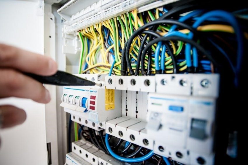
Identifying blown fuses or tripped circuit breakers in the John Deere L120 is crucial for maintaining its electrical system. Use the wiring diagram to locate the fuse box and inspect each fuse for visible damage or breaks in the filament. A multimeter can also test for continuity. Tripped breakers may reset, but persistent issues indicate deeper electrical problems. Always disconnect the battery before working on fuses to ensure safety.
Prevent future issues by avoiding overloaded circuits and checking for short circuits or faulty components. Regular inspections can help maintain reliability and performance.
3.2 Diagnosing Faulty Wire Connections
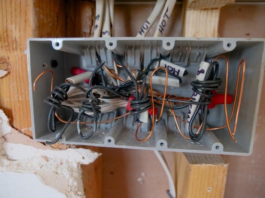
Diagnosing faulty wire connections in the John Deere L120 requires a systematic approach. Use the wiring diagram to trace circuits and identify potential connection points. Inspect connectors and wires for signs of corrosion, damage, or wear. A multimeter can test for continuity or short circuits between terminals. Clean corroded connections or replace damaged wires. Ensure all connectors are securely fastened. Regular inspections help prevent electrical failures and ensure the tractor operates reliably. Always disconnect the battery before working on wiring to avoid shocks or short circuits.
3.3 Repairing or Replacing Damaged Wires
Repairing or replacing damaged wires in the John Deere L120 requires careful attention to detail. Use the wiring diagram to identify the affected circuit and locate the damaged wire. Disconnect the battery before starting repairs. Strip the damaged ends and splice in new wire, ensuring secure connections. Apply heat shrink tubing or electrical tape for insulation. If a wire is severely damaged, replace it entirely with the correct gauge and color-coded wire. Always test the circuit with a multimeter after repairs to ensure proper functionality.
3.4 Checking the Solenoid and Starter Motor
To diagnose issues with the solenoid and starter motor, refer to the John Deere L120 wiring diagram. First, disconnect the battery for safety. Use a multimeter to test the solenoid for continuity and ensure it activates when the ignition switch is turned on. Check the starter motor for proper power supply and inspect for physical damage. If the solenoid fails to engage, it may need replacement. Similarly, a faulty starter motor should be repaired or replaced to restore functionality.

Understanding the Electrical System Layout
The John Deere L120 wiring diagram reveals the electrical system’s structure, highlighting the battery, ignition switch, solenoid, and sensors. It illustrates wire colors, connectors, and grounding points, ensuring proper connections for optimal functionality and safe repairs.
4.1 Main Control Board and Its Functions
The main control board is the central hub of the John Deere L120’s electrical system, housing essential components like the ignition switch, solenoid, and voltage regulator. It regulates power distribution to various subsystems, ensuring proper operation of the tractor’s electrical functions. The board connects to sensors, safety switches, and the PTO clutch, acting as the nerve center for all electrical activities. Understanding its layout and functions is crucial for diagnosing and repairing electrical issues effectively, as outlined in the wiring diagram.
4.2 Wire Color Coding and Their Functions
The John Deere L120 wiring diagram uses standardized wire color coding to identify circuit functions. Red wires typically power key components like the ignition and solenoid, while yellow wires often connect to sensors and safety switches. Green wires are commonly used for ground connections, ensuring proper electrical flow. Black wires usually indicate negative or ground paths. This color coding system simplifies troubleshooting and repairs, allowing users to quickly trace circuits and identify potential issues. The wiring diagram provides a clear guide to understanding these color codes.
4.3 Connector and Terminal Identification
The John Deere L120 wiring diagram provides clear labels for connectors and terminals, ensuring easy identification. Connectors are color-coded and labeled by function, such as ignition, PTO, and sensor connections. Terminals are marked with their corresponding wire colors and circuit roles. The diagram highlights key connectors like the ignition switch and solenoid, as well as the main control board terminals. This detailed labeling helps users trace connections accurately, simplifying repairs and maintenance by reducing confusion and ensuring proper wiring setups.
4.4 Grounding Points and Their Importance
The John Deere L120 wiring diagram emphasizes the importance of grounding points for proper electrical system function. Grounding ensures safe current flow and prevents electrical hazards. Key grounding points are typically located on the tractor’s frame, battery, and major components. Improper grounding can lead to system malfunctions, erratic behavior, or even safety risks. The diagram highlights these points, ensuring users can identify and verify them during repairs or maintenance, maintaining system reliability and operator safety.

Safety Precautions When Working with Wiring
Always wear protective gear like gloves and safety glasses when handling wiring. Ensure the tractor is on a level surface and turn off the ignition.
5.1 Disconnecting the Battery Before Repairs
Disconnecting the battery is crucial before starting any repairs to prevent accidental ignition or electrical shocks. Locate the battery, typically under the hood or seat. Wear protective gear like gloves and safety glasses. Always disconnect the negative (black) terminal first, followed by the positive (red) terminal. Ensure all power sources are off and the tractor is in park. This step ensures safety and prevents potential damage to the electrical system during repairs.
5.2 Using Proper Tools for Wiring Repairs
Using the correct tools ensures safe and efficient wiring repairs. Essential tools include a multimeter for testing circuits, wire strippers for removing insulation, and crimping tools for securing connections. Screwdrivers and pliers are also necessary for accessing and tightening components. Optional tools like heat guns or soldering irons may be needed for more complex repairs. Always use tools suitable for electrical work to avoid damage or safety risks. Proper tools ensure accurate diagnostics and reliable fixes.
5.3 Avoiding Short Circuits and Electrical Shocks
Avoiding short circuits and electrical shocks is crucial for safety. Always disconnect the battery before starting repairs to prevent power surges. Use insulated tools to handle live wires and avoid touching electrical components with bare hands. Ensure all connections are secure and free from damage. Never overload circuits, as this can cause overheating or sparks. Follow the wiring diagram to identify proper connections and avoid mismatches. Grounding points should be checked to ensure they are functional and secure. Proper precautions prevent accidents and ensure safe repairs.
5.4 Following Manufacturer Guidelines
Adhering to manufacturer guidelines is essential for safe and effective repairs. John Deere provides detailed instructions in the wiring diagram PDF to ensure proper handling of electrical components. Always refer to the official manual for specific procedures and safety protocols. Using unauthorized methods or ignoring recommendations can lead to system damage or safety risks. Compliance with guidelines ensures compatibility and prevents voiding warranties. Rely on John Deere’s expertise for accurate and reliable repair practices.

Tools and Materials Needed for Wiring Repairs
Essential tools include a multimeter, wire strippers, crimping tools, and replacement fuses. Materials like electrical tape and heat shrink tubing are vital for secure, durable repairs.
6.1 Multimeter for Testing Electrical Circuits
A multimeter is crucial for diagnosing electrical issues in the John Deere L120. It measures voltage, current, and resistance, helping identify faulty circuits or components; Use it to test battery voltage, check for continuity in wires, and verify the operation of switches and sensors. This tool ensures accurate troubleshooting, preventing further damage and ensuring safe repairs. Always refer to the wiring diagram to understand which circuits to test and their expected readings.
6.2 Wire Strippers and Crimping Tools
Wire strippers and crimping tools are essential for repairing and maintaining the John Deere L120’s wiring. Strippers safely remove insulation without damaging wires, while crimping tools secure connections. Use manual or automatic strippers for precise wire preparation. Crimpers ensure reliable terminals and connectors. These tools help prevent wiring damage during repairs, ensuring durable and safe electrical connections. Proper use maintains the integrity of the tractor’s electrical system, as outlined in the wiring diagram.
6.3 Replacement Fuses and Relays
Replacement fuses and relays are crucial for maintaining the John Deere L120’s electrical system. Fuses protect circuits from overcurrent, while relays control power distribution to components. The wiring diagram identifies fuse locations and relay connections, ensuring correct replacements. Always use fuses and relays with the correct specifications to avoid damage. Replacing blown fuses or faulty relays promptly prevents system malfunctions and keeps the tractor operational. Proper installation ensures safety and optimal performance, as detailed in the wiring diagram guide.
6.4 Electrical Tape and Heat Shrink Tubing
Electrical tape and heat shrink tubing are essential for protecting and insulating wires in the John Deere L120. The wiring diagram highlights their use in securing connections and preventing damage. Electrical tape provides a flexible, weather-resistant barrier, while heat shrink tubing offers a durable, long-lasting seal. Properly applied, these materials ensure reliability and safety in the tractor’s electrical system. Always follow the diagram’s guidance for correct application to maintain optimal performance and avoid potential hazards. These tools are vital for professional-grade repairs.

Step-by-Step Guide to Reading the Wiring Diagram
Start by identifying key symbols and color codes. Locate the main components like the battery, ignition, and solenoid. Trace circuits to understand connections and power flow. Use the diagram to pinpoint switches and sensors, ensuring a clear understanding of the electrical system for effective troubleshooting and repairs.
7.1 Identifying the Main Components
Begin by locating the battery, ignition switch, solenoid, and starter motor. Identify sensors, fuses, and relays. Note the main wiring harness and grounding points. Understand the power take-off (PTO) clutch wiring and safety switches; Familiarize yourself with the voltage regulator and charging system components. Recognize the color-coded wires and their functions. This step ensures a clear understanding of the tractor’s electrical layout, making it easier to trace circuits and diagnose issues effectively.
7.2 Understanding Wire Colors and Codes
Wire colors in the John Deere L120 wiring diagram represent specific functions. Red wires typically indicate positive battery connections, while yellow wires connect to the ignition circuit. Black wires are usually ground wires, and green wires often link to sensors. Understanding these color codes helps in identifying circuits and components quickly. The diagram serves as a legend, explaining the role of each wire color. This standardized system ensures consistency and simplifies troubleshooting and repairs by providing a clear visual guide to the electrical system’s layout and connections.
7;3 Tracing Circuits and Connections
Tracing circuits and connections in the John Deere L120 wiring diagram involves identifying the path of electrical current. Start by locating key components like the ignition switch, solenoid, and starter motor. Follow the wires as they connect these parts. Use the wiring diagram to map out the circuit, understanding how power flows from the battery through the ignition switch to the solenoid and finally to the starter motor. This process aids in diagnosing electrical issues and ensures proper repairs by visualizing the system’s layout.
7.4 Identifying Switches and Sensors
Identifying switches and sensors in the John Deere L120 wiring diagram is crucial for understanding their roles in the tractor’s electrical system. The ignition switch, seat switch, and PTO sensor are key components. Use the diagram to locate these parts and their connections. Switches are often labeled with their functions, while sensors may be represented by symbols. Understanding their placement and wiring helps in diagnosing issues like faulty starts or PTO engagement problems, ensuring accurate repairs and maintaining safety.

Common Mistakes to Avoid When Using the Wiring Diagram
Common mistakes include misidentifying wire colors, overlooking grounding points, and ignoring safety precautions. Always cross-reference the diagram with the tractor’s actual wiring to avoid errors;
8.1 Misidentifying Wire Colors and Codes
Misidentifying wire colors and codes is a common mistake that can lead to electrical issues. Always cross-reference the wiring diagram with the tractor’s actual wiring to ensure accuracy. Pay attention to specific color codes, as they indicate different functions, such as power, ground, or sensor connections. Using the wrong wire color can result in short circuits, damaged components, or system malfunctions. Refer to the official John Deere L120 wiring diagram PDF for precise information to avoid costly errors during repairs or maintenance.
8.2 Overlooking Grounding Points
Overlooking grounding points is a critical error that can disrupt the entire electrical system. Proper grounding ensures safe current flow and prevents damage from voltage surges. Always verify grounding connections using the wiring diagram, as improper grounding can lead to malfunctions, electrical shocks, or component failure. Neglecting this step can compromise safety and system performance, making it essential to carefully inspect and validate all grounding points during repairs or diagnostics to maintain the tractor’s reliability and functionality.
8.3 Incorrectly Replacing Fuses or Relays
Incorrectly replacing fuses or relays can lead to electrical system malfunctions or even damage to components. Always use the wiring diagram to identify the correct fuse or relay type and rating. Using the wrong specifications can cause circuits to overload or fail to function properly. Refer to the diagram to locate and replace fuses accurately, ensuring the electrical system operates safely and efficiently. Testing the circuit after replacement is recommended to confirm proper functionality.
8.4 Ignoring Safety Precautions
Ignoring safety precautions when working with the John Deere L120 wiring diagram can lead to electrical shocks or damage to the tractor. Always disconnect the battery before repairs and use proper tools to avoid short circuits. Failure to follow safety guidelines can result in personal injury or system malfunctions. Ensure all precautions are taken to maintain safety and prevent accidents during wiring diagram usage. Adhering to manufacturer guidelines is essential for safe and effective repairs.

Resources for Downloading the John Deere L120 Wiring Diagram PDF
The John Deere L120 wiring diagram PDF can be downloaded from the official John Deere website, repair forums, or local dealerships, ensuring authentic and trusted sources.
9.1 Official John Deere Website and Manuals
The official John Deere website provides authentic resources, including the L120 wiring diagram PDF, service manuals, and parts diagrams. Users can access these by visiting the John Deere website, navigating to the support or manuals section, and searching for the L120 model. The official manuals are comprehensive, offering detailed schematics and repair guides; Downloading from the official source ensures accuracy and reliability, making it the most trusted option for technicians and DIY enthusiasts alike.
9.2 Online Marketplaces and Repair Forums
Online marketplaces like eBay and Amazon often host third-party sellers offering the John Deere L120 wiring diagram PDF. Repair forums and communities, such as Reddit or specialized tractor repair groups, provide valuable resources and discussions. Users can search for threads or posts sharing the diagram directly. Additionally, platforms like ManualsLib or Scribd may have downloadable versions. Always verify the source’s reliability to ensure the document’s accuracy and safety before downloading.
9.3 Third-Party Repair Manual Websites
Third-party websites like ManualsLib, Scribd, and RepairManuals.com often provide access to the John Deere L120 wiring diagram PDF. These platforms host a wide range of repair manuals and technical documents. Users can search for and download the wiring diagram, often for free or at a low cost. Ensure the source is reliable and verify the document’s authenticity to avoid incorrect or incomplete information. These sites are convenient for quick access to essential repair resources.
9.4 Local Dealerships and Service Centers
Local dealerships and service centers are excellent sources for obtaining the authentic John Deere L120 wiring diagram PDF, ensuring accuracy for maintenance and repairs. They offer both printed and digital versions, catering to different user needs and preferences. The knowledgeable staff can provide guidance and support, making the process smoother and less overwhelming. Purchasing from them guarantees that the diagrams are current and compliant with John Deere’s standards. Visiting a local dealership is a convenient and reliable way to acquire the necessary resources without the risks of third-party websites.
The John Deere L120 wiring diagram is essential for safe and effective maintenance. Always follow safety guidelines and use authentic resources for reliable repairs.
10.1 Summary of Key Points
The John Deere L120 wiring diagram is a crucial resource for understanding and maintaining the tractor’s electrical system. It provides detailed layouts of circuits, components, and connections, such as the battery, ignition switch, solenoid, and sensors. This guide helps users troubleshoot issues like blown fuses or faulty wires and ensures safe repairs by following proper procedures. Always refer to official John Deere manuals or trusted sources for accurate and reliable information to avoid errors and ensure optimal performance.
10.2 Final Tips for Effective Use of the Wiring Diagram
Always use the correct tools, such as a multimeter, to test circuits and ensure proper connections. Cross-reference the wiring diagram with the tractor’s manual for accuracy. Organize wires by color coding and label them for clarity. Test circuits incrementally to avoid overload. Document any modifications for future reference. Prioritize safety by disconnecting the battery before starting repairs. Following these tips ensures efficient and safe use of the John Deere L120 wiring diagram for maintenance and repairs.
10.3 Encouragement to Practice Safe and Proper Repairs
Always prioritize safety by disconnecting the battery and using proper tools. Follow the wiring diagram and manufacturer guidelines to avoid electrical shocks or damage. Double-check connections and test circuits before restarting the tractor; Regularly inspect wires and components for wear. Keep the diagram handy for quick reference. By practicing safe and proper repairs, you ensure the longevity and reliability of your John Deere L120, while also protecting yourself from potential hazards.

